
Digital Newsletter
Each week our editor Phil Alsop rounds up the most popular articles, videos and expert opinions. We compile this into a Digital Newsletter and send it straight to your inbox every week.
Digital Magazines
We'll let you know each time a new edition of Digitalisation World is released so that you're always kept up-to-date with the latest and greatest news and press releases.
Video Magazines
The Digitalisation World Video magazine contains the latest Zoom interviews with experts in the industry.
Optical fiber lasers operating at high power levels can pose risks to person and property. To reduce the likelihood of accidents, Meta and Scintacor joined hands to develop an infra-red (IR) radiation detector that operates between 1400nm -1600nm, at power levels greater or equal to 0dbm and is not triggered by lasers operating at other wavelengths. These detectors are used for higher-power line-side optics, amplifiers, or pump lasers (such as Raman pumps).
Background
Using laser light from one or more lasers simultaneously, fiberoptic networks transmit huge quantities of information. Many of these lasers operate at high powers and have the potential to cause personal injury or property damage. The wavelengths used are in the infra-red part of the electromagnetic spectrum and the light is invisible to the unaided human eye, meaning that a laser is unlikely to be observed before damage is caused.
Even with stringent working procedures (Method of Operations Procedures or “MOPs”) employed at data centers and related facilities, which require high-power lasers to be turned off before performing maintenance work, there remains a significant risk that persons maintaining the network infrastructure could be exposed to high-power laser radiation, causing significant harm.
This report summarizes the development of a new device, named a “laser safety detector”, that can be utilized to perform an additional check to verify that lasers are not operating, as part of a MOP.
Meta is developing a laser safety program, including safety for many laser sources, with the largest number being laser fiber sources used in data networks. The laser safety detector was designed to identify laser sources that are operating whilst also re-enforcing awareness of the risk.
Existing Safety Controls
Several measures and tools already exist to manage the risk of injury or damage from unintentional exposure to high-power lasers. These include safety control procedures, electronic laser detectors and IR detector cards. The impact and suitability of each of these is discussed.
Safety Control Layers
As part of their standard operating procedures (e.g., Method of Operation Procedures or MOP), each organization will have risk assessments, training protocols etc. to direct human activities safely. While these can be very robust, it is required to ensure the operating environments are as safe as possible, through the provision of suitable tools.
Within the typical operational procedures, we add a step: after confirmation that a laser is disabled and removal of the fiber, a safety laser detector is used to confirm the laser is off. This step brings both awareness of the risk and positive confirmation that the laser is off or negative confirmation that the laser was not turned off and it is not safe to proceed with work until it is turned off.
Electronic laser detectors
Existing electronic fiber detectors are marketed by a number of manufacturers. These operate by bending an optical fiber beyond its customary bend radius and monitoring laser radiation that is emitted by the waveguide (see Figure 1).
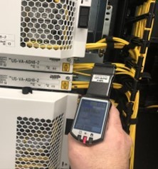
Figure 1 : Active in-use fiber detection on a line side DWDM system fiber. Image supplied by Meta
While these electronic tools can be used to confirm there are no live lasers, there are several drawbacks.
• Some electronic fiber tools will detect any laser in use. Thus, they will also detect Optical Service Channel (OSC) lasers that are not considered a safety risk due to their lower power. Therefore, there is a risk of a false trigger event.
• The tools only operate on small fiber bundles. Although they are designed to work on simplex or duplex (ripcord or single sheathed) OS2 (Single Mode Fiber), they, in practice, operate on low strand count ribbon fiber such as 12-strand ribbons commonly used with MPO or MPT connectors in data center SMF applications. Large fiber bundles from 24 to over 6,000 strands of glass cannot be tested by these tools.
• Electronic tools are costly, not easily portable and can require a steep learning curve for proper use.
• A major issue for electronic devices is sensitivity to environmental conditions, and as such, they are not intended for the extreme temperature and humidity variations that can be found in data communication centers. They are not intended for outside plant use as screens are not visible in sunlight and the batteries have a finite lifespan.
Laser detection card
Laser detection cards are a passive solution which require no power source (see Figure 2). They can be used outside and have a large active area for use on large fiber bundles, as well as single fibers. However, these cards have a broadband response and will also detect low power, OSC lasers that pose no risk. In addition, they are typically plastic, which raise concerns about their durability when exposed to high-power lasers.
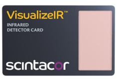
Figure 2 : Laser Detection card example image
Identification of Safety Tool requirements
It was determined there was a need to verify when a fiberoptic cable is not active, that is, that the laser has been shut down and therefore, is safe to handle for maintenance activities or for end-oflife diagnosis.
Meta purchased and tested off the shelf laser detector cards, including the Visualize IR card from Scintacor. They were tested in various working conditions, indoor and outdoor, with different systems from multiple manufacturers of telecommunications equipment.
Using this test information from existing products, a set of product and technical requirements were determined. Some requirements from Meta, that came from the testing are highlighted below.
Material composition
The detector should be made of materials which suitably withstand normal utilization, involving exposure to laser radiation, as well as indoor and outdoor temperature variations.
Given the energy density of an incident laser, it is likely that plastic materials would not be acceptable for the operating area of the detector. Compounded with expected temperature exposure and typical handling by operators, more suitable materials may be glass or ceramic substrates.
Although direct exposure to the beam is the major concern, eyes can also be damaged by reflected laser radiation from a fiber source. To avoid eye injury stemming from reflection, the non-operating area of the detector should either not reflect the laser radiation at the wavelengths specified for use, or substantially reduce the power of the reflected laser by loss including absorption or scattering (diffraction).
Operating Temperature Range
Meta operates datacenters as far north as Lulea, Sweden and as far south as Singapore and has datacenters in deserts (Los Lunas, NM).
There is a wide range of operating conditions across datacenters globally. Indoor temperatures, although “controlled”, operate in a wide range of an expanded datacenter operating envelope (encouraged by ASHRAE). Temperatures vary from intake to exhaust, and although rare, there are circumstances under which the device will be used in the “hot aisle” where exhaust temperatures can reach over almost 160°F (70°C) at the rear of operating equipment.
Therefore, it was determined that the detector device should be operable invariant of relative humidity (RH) and be easily cleaned.
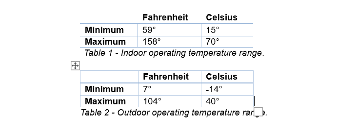
1. Material choice is dependent on the product lifetime with respect to changes in environmental conditions the device may experience. For example, the device may be stored inside (22°C), placed in an operator’s pocket (37°C), or more severely, used in a hot aisle (70°C). It may then be used outdoors in a vault where temperatures are as low as -14°C, creating a ΔT 84°C. Additionally, varying humidity and temperatures may cause high material stress and condensation on the device.
Based on the varying degrees of climate, the required operating temperatures for both indoor and outdoor conditions are shown in Table 1 and Table 2.
Laser Power
Laser power varies widely across systems depending on the number of channels in use, modulation techniques and the use of amplifiers. For simplicity we calculated four maximum power values.
Power is distributed across the diameter of the inner core of the SMF with a far field angle at less than 5°. (Full calculations may be requested from the authors).
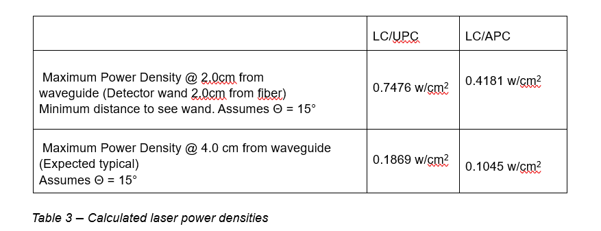
Power Density
We calculated the incident power density at no distance from the semiconductor laser source transmitter interface (which is typically a bulkhead on a line card for such an optical transmitter) from an SMF waveguide with LC/UPC or LC/APC connector. In the most extreme scenario, an operator may hold the laser safety detector directly to the fiber.
We then calculated the maximum power at a minimum distance of 2.0 cm from the fiber to the detector. Although it will be held by hand and could even touch it, such events will be ephemeral. The device itself must be designed to suitably withstand the maximum power laser-radiation.
Considering fiber sizes, cleave angles, transmitter characteristics and losses the following maximum power densities were calculated (as seen in Table 3). (Full calculations may be requested from the authors).
Wavelength sensitivity
The detector device is needed to detect lasers in the C-Band and L-Band (above 1531nm) and not to fluoresce for the frequency range and power levels of the lasers in the O-Band, E-Band, or SBand (See Figure 3). Technicians who want to identify if the transmit laser is in use for these systems can use existing off-the-shelf broad-spectrum cards such as the Scintacor Visualizer.
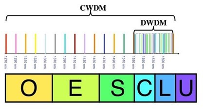
Figure 3 : Wavelength spectrum of laser communication bands.
Source - https://www.thefoa.org/tech/ref/basic/SMbands.html
Detection Area
The surface area of the laser detector wand should be at least the size of the largest fiber bundles. Although typical DWDM applications run on small strand counts (12-, 24-, 48-, 96- strand bundles), campus bundles are possible, with 3456 or 6912 strands (see Figure 4). The expected surface area is 25% larger than current diameter 1.3” which is 34mm cables or 1.5” 42mm.
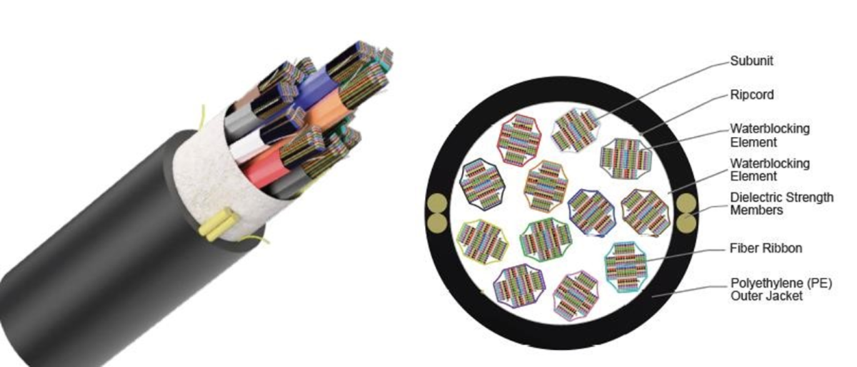
Figure 4 : An example fibre-optic bundle (Rocket Ribbon 3456 SMF-28 Ultra Fiber (OS2)). Source - Corning Inc.
Portability
For convenience and ensured safety, it is preferred for a planar surface detector such as a “card” or “wand” to be held by an operator in line with and at a distance from, an exposed fiber cut, cleaved, or polished surface. The card should be easy to transport among areas or placed in a location that is easily accessible to all workers.
Cost
While cost concerns should be second to improved safety, a reasonable cost is required to encourage maximum availability and use.
Developed Laser Detector Device
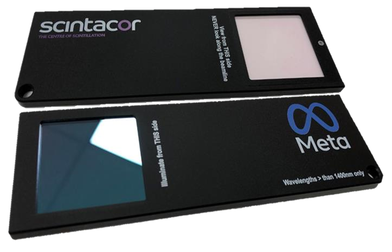
To satisfy the product requirements outlined above, Scintacor Ltd developed a handheld detector for fast and reliable Infra-red (IR) radiation detection (An operating diagram is shown in Fig. 5).
While the initial desire was for all laser light at shorter wavelengths than C-band to not trigger a response, it was decided that a slightly broader wavelength response would be used, to have very high confidence that the wavelengths of interest would not be excluded by the long-pass filter. Therefore, the device was designed to operate with high-power telecommunication lasers with excitation wavelength between 1400nm and 1600nm and powers above 0dBm.
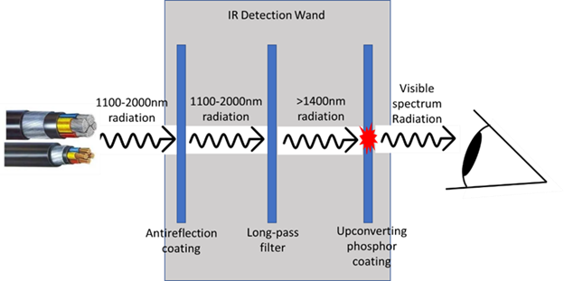
Figure 5. A simplified diagram of Scintacor IR detection wand. Lasers from fiber bundle first pass through an anti-reflection coating, next the long-pass filter transmits only laser light with wavelengths higher than 1400nm which interacts with upconverting IR phosphor (which reacts to wavelengths <1600nm), emitting a visible red light that can be observed by the operator.
A plastic housing was designed for the detector to be easily held in-hand and reduce the drop-risk. The acrylic design withstands most small impacts, and the 2-piece mechanical design contains the active surfaces sub-flush of the external surfaces, thus affording protection to the glass components. The detection phosphor coating, anti-reflection coating, and long pass filter are deposited on a glass substrate and manufactured from inert materials capable of withstanding the expected working environments e.g. temperature and humidity variations. Both outer faces can easily be wiped clean with a damped cloth without affecting performance.
The detection area of 36mm x 36mm was chosen to provide coverage of fiber bundles of up to 34mm (1.3”) diameter.
To address the safety requirements, particularly those associated with accidental reflections of highpower laser beams, an anti-reflection coating was added as an integral part of the detector, minimizing stray reflections of incoming laser beams. The anti-reflection coating, composed of zirconia and silica layers, is applied to the outer glass surface, giving less than 2% reflection in the 1100 – 2000nm range. Additionally, the main body of the wand was designed from a machinable acrylic that has been produced in a black, silk finish to minimize reflections, as is good practice for equipment used with laser light.
Scintacor’s existing range of IR visualization products use an upconverting phosphor that emits visible light when irradiated by a range of near infra-red (NIR) and infra-red radiation (IR), mainly at 870-1070nm, and 1500-1590nm bands, respectively. However, to prevent unwanted false positive indications, the detector was designed to only respond to wavelengths longer than 1400nm (in the C, L, & U bands).
To only detect IR lasers operating at above 1400nm, a long-pass filter was chosen to prevent unwanted laser beams from reaching the upconverting phosphor. The characteristic of the selected long pass filter is shown in Fig. 6.
Further details of the device are disclosed in Scintacor’s UK patent application [1]
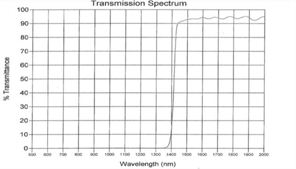
Figure 6. Long-pass filter characteristic with cut-off below1400nm.
Performance Verification
The intended application is to be the final checkpoint in what should be a series of steps, outlined in specific Methods of Procedure (MOP) when conducted by Meta or its service providers.
To demonstrate the Scintacor IR detection wand capabilities and functionality required by the product specification, several tests have been carried out.
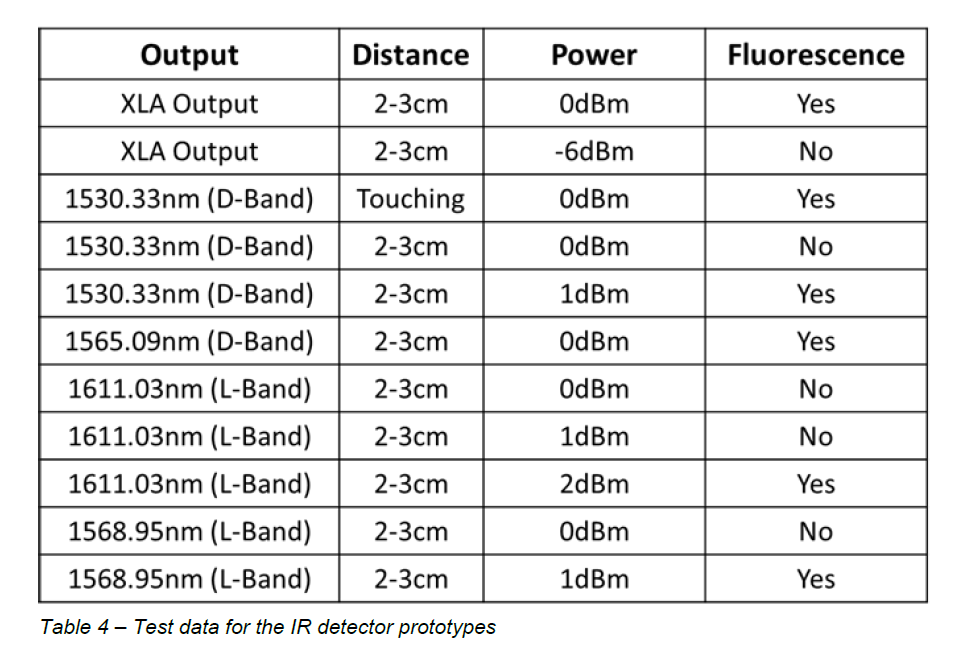
In Test 1, DWDM line amplifier equipment with C-Band cards has been used. The target power has been set at 0dBm. The side fiber TX was unplugged, and the IR detector was held 2-3cm from the end. Two tested prototypes displayed visible fluorescence, (see Fig. 7). At a power value of -6dBm the laser detection wand did not show any visible fluorescence. Test data is summarized in Table 4.
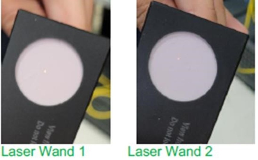
Figure 7. Two IR detection wand prototypes show visible fluorescence when exposed to 0dBm IR excitation source.
In Test 2, DWDM system with C-Band sled was used. The initial Tx power was set up at 0dBm and the detector was placed 2-3cm away from the TX fiber. This test was carried out for 1530.33nm and 1565.09nm wavelengths.
In Test 3, DWDM system with L-Band sled was used. The initial Tx power was set up at 0dBm and the detector was placed 2-3cm away from the TX fiber end. This test was carried out for 1611.03nm and 1568.95nm wavelengths. At 1611.03nm emission there was no visible fluorescence for 0dBm and 1 dBm. After increasing the power to 2dBm, the fluorescence was visible. At 1568.95nm emission there was no visible fluorescence for 0dBm but after increasing the power to 1dBm, the fluorescence was present.
Summary
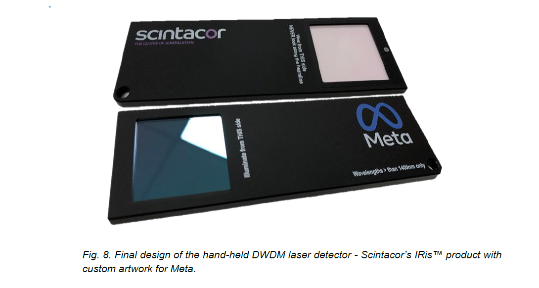
To address the laser safety program introduced by Meta, Scintacor developed the IRis™ safety detection wand. The initial tests demonstrated that the IRis™ is an effective tool at quickly determining if a DWDM line side or pump laser is on or off. It has been designed to detect laser power of 1dBm (approximately 1.2 milliwatts) or above, where the risk of injury for the operating personnel is the greatest. A picture of a fully operational IRis™ detector is shown in Fig. 8. To satisfy the safety requirements outlined in Meta’s product requirements, the final product features are:
References
[1] Scintacor patent application No. 2118955.0
https://scintacor.com/iris-safety-wand/